



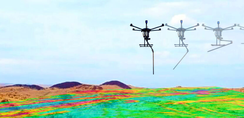
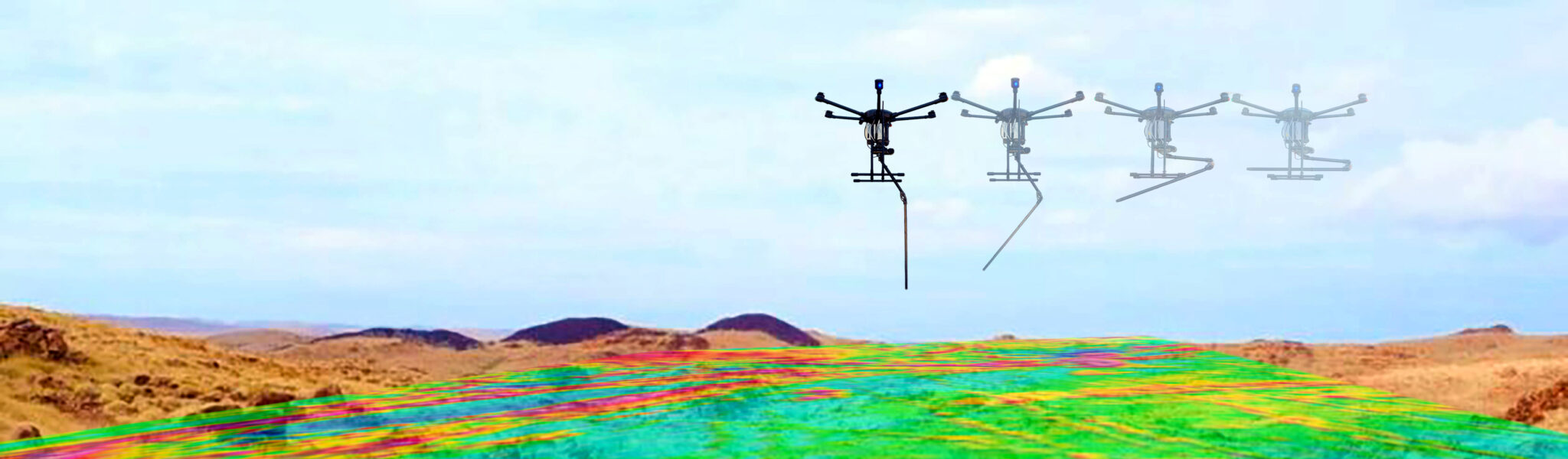
In brief: Airborne magnetometry is a rapid, non-invasive method for mapping magnetic contrasts associated with rock units, faults, magnetically responsive mineralization and buried ferrous objects. UAV platforms make denser, lower-altitude surveys possible, but reliable results still depend on flight design, terrain clearance, platform-noise control and disciplined data processing.
What is airborne magnetometry?
The magnetic field measured at any location is a combination of the Earth’s main field, time-varying external contributions, geological signals and environmental or instrumental noise. Subsurface rocks produce different magnetic responses according to their mineral content, magnetic susceptibility and remanent magnetization. A sensor flown along systematic survey lines records these variations as profiles that can later be corrected, levelled and gridded into interpretable maps.
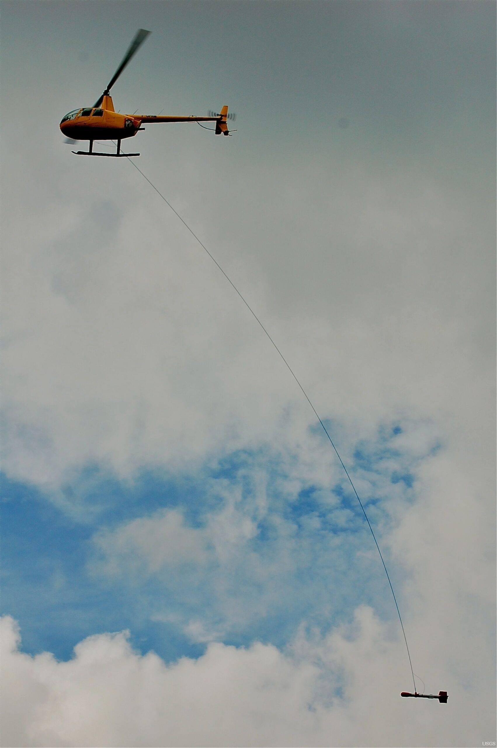
The U.S. Geological Survey notes that airborne magnetic data can reveal changes in rock type, ancient faults and other geological features, including signatures associated with potential mineral deposits. At local scale, lower sensor altitude and tighter line spacing may resolve shallower and smaller targets that would be smoothed in a high-altitude regional survey.
Why use UAVs for magnetic surveys?
Manned aircraft remain essential for extensive regional programs. For detailed local projects, however, a UAV can bridge the gap between walking surveys and conventional airborne acquisition. It can follow repeatable lines over difficult terrain while reducing the need for crews to cross steep slopes, unstable ground, dense vegetation or potentially hazardous areas.
- Higher spatial resolution: bringing the sensor closer to a shallow source preserves shorter-wavelength detail.
- Efficient coverage: automated, parallel flight lines can cover a dense grid faster than a ground crew.
- Improved safety: fewer personnel need to enter inaccessible or risky terrain.
- Repeatability: route, speed, altitude and line direction can be planned and repeated.
- Lower logistics: deployment is often simpler for small and medium-sized projects.
Four decisions that define survey quality
1. Sensor height above terrain
Signals from shallow targets decay rapidly with distance. The relevant quantity is the sensor’s true clearance above ground, not merely the UAV altitude. Flying lower is not automatically better: terrain, vegetation, safety margins, sensor motion and aviation restrictions must be balanced against the desired resolution.
2. Line spacing and orientation
Line spacing should reflect expected target size, depth and survey altitude. Lines that are too wide may miss narrow anomalies; excessive density increases flight time and data volume without proportional benefit. Tie lines crossing the production lines provide an independent control for levelling.
3. Speed, sampling rate and timing
Along-line sample spacing depends on groundspeed and effective sampling rate. Poor synchronization between the magnetometer and positioning system can shift or stretch an anomaly. Accurate time alignment among magnetometer, GPS and IMU is therefore fundamental.
4. Flight stability and environment
Rapid changes in pitch, roll and yaw, wind-driven sensor motion, altitude changes and tight turns can introduce unwanted variations. Forward and reverse lines should be checked for heading effects, altitude consistency and levelling differences.
The central engineering challenge: UAV magnetic noise
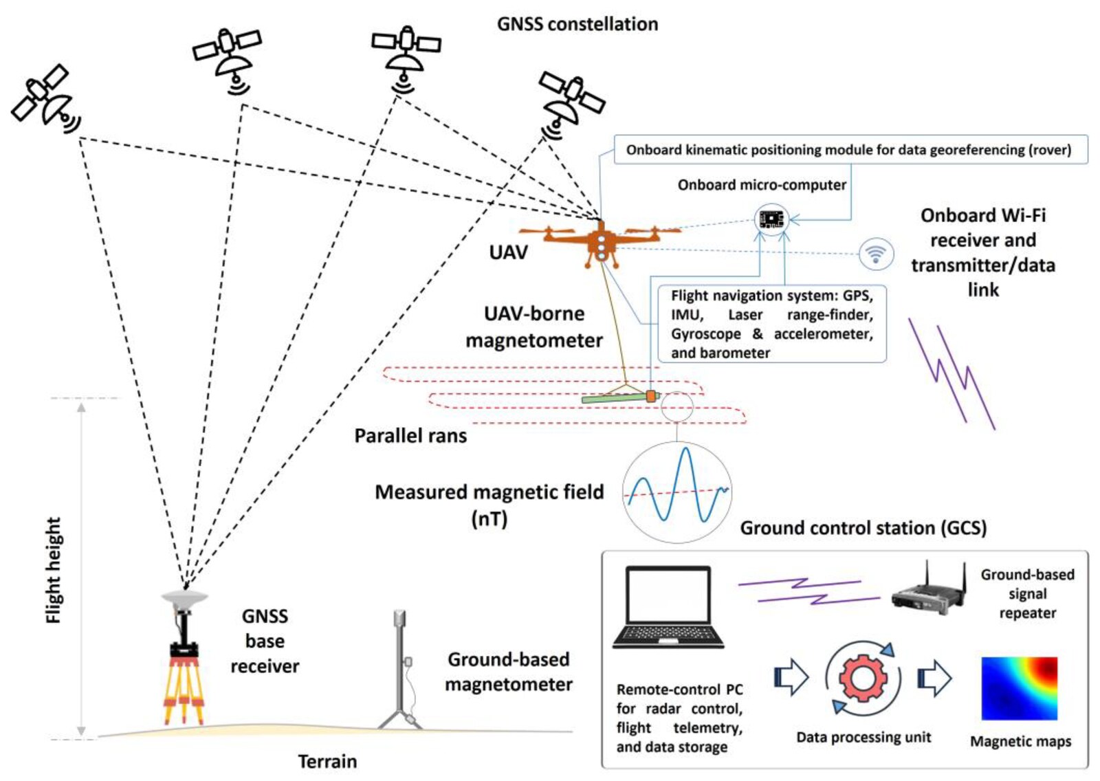
Brushless motors, permanent magnets, ESC switching currents, battery cables, power converters, steel fasteners and current changes during manoeuvres can all contaminate the measurement. Experiments by the Technical University of Denmark identified current-carrying cables between the battery and flight controller as a major source of dynamic interference. A sensitive sensor alone is not enough; the mechanical and electrical architecture of the complete system must be designed for low-noise operation.
Keep the magnetometer away from motors, power cables and high-current electronics.
Control structural materials, fasteners and connectors.
Use GPS and IMU data to understand motion-related effects.
Characterize the platform before a production survey.
A professional workflow from field to map
- Define the target: expected size, depth, geology and required level of detail.
- Assess the site: map power lines, fences, vehicles, steel infrastructure and flight restrictions.
- Design the mission: select height, production lines, tie lines, speed and sample rate.
- Run pre-flight checks: verify timing, GPS, memory, telemetry, batteries and sensor status.
- Perform field QC: confirm coverage, altitude stability, valid samples and consistency between reciprocal lines.
- Process the data: remove invalid records, correct temporal and reference-field effects, level the lines and grid the observations.
- Interpret: use total field, gradients and suitable transforms such as derivatives, analytic signal or reduction to the pole according to the objective.
Total field, vector data and gradients
| Data type | Main advantage | Key consideration |
|---|---|---|
| Total field | Widely used and suitable for regional comparison | Sensitive to temporal field variations |
| Three-axis vector | Directional information and attitude-aware analysis | Requires careful orientation control and calibration |
| Gradient | Emphasizes local changes and suppresses some common temporal effects | Sensor baseline and alignment must remain stable |
Key applications
- Mapping magnetite-, pyrrhotite- and other magnetically responsive mineralization;
- Tracing faults, dykes, lithological contacts and concealed structures;
- Locating buried pipelines, steel infrastructure and ferrous targets;
- Supporting authorized UXO, archaeological, engineering and environmental investigations;
- Complementing ground data and prioritizing detailed follow-up or drilling.
How ArtaMag addresses the workflow
ArtaMag is a TRL 8 UAV-borne magnetometry platform developed by Arta Novin Technology. It combines three-axis fluxgate sensors, integrated GPS and IMU, internal memory, live telemetry and simultaneous local recording in a rugged package weighing less than 2 kg.
Its intelligent retractable sensor mechanism moves the measurement assembly away from major UAV noise sources during acquisition while improving handling during take-off and landing. Data are brought into the PRISMAG ecosystem for quality control, processing and 2D/3D outputs. The central design philosophy is that hardware, mission planning and processing must operate as one measurement chain.
Planning an airborne magnetic project?
Share your survey area, target and expected output with Arta Novin’s technical team to define the appropriate altitude, line spacing and flight platform.
Explore ArtaMagRequest ConsultationReferences
- U.S. Geological Survey, Geophysical Mapping and Low-flying Research Helicopter.
- Jirigalatu et al. (2021), Experiments on magnetic interference for a portable airborne magnetometry system using a hybrid UAV, GIMDS, CC BY 4.0.
- Dadrass Javan et al. (2025), Unmanned Aerial Geophysical Remote Sensing: A Systematic Review, Remote Sensing, CC BY 4.0.
- Mu et al. (2020), Automatic Detection of Near-Surface Targets for UAV Magnetic Survey, Remote Sensing.
- Macharet et al. (2016), Autonomous Aeromagnetic Surveys Using a Fluxgate Magnetometer, Sensors, CC BY 4.0.








Leave a Reply